|
|
Main / STM1 compliant DVB-ASI TS multiplexers-demultiplexers / PMTS-3601
PMTS-3401(CW##) four DVB-ASI TS to STM1 optimizing multiplexer, optical and electrical STM1 main and auxiliary outputs |
PRELIMINARY
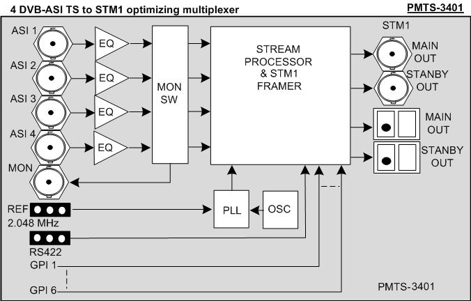
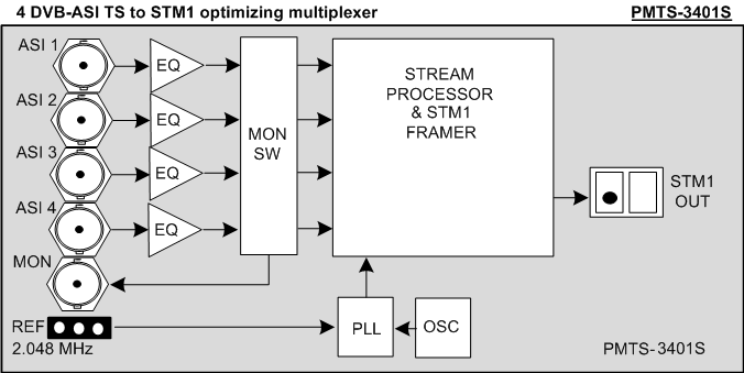
PMTS-3401(CW##) series “four DVB-ASI transport streams to STM1” optimizing multiplexer with optical and electrical main and auxiliary outputs accepts up to four DVB-ASI streams to multiplex them into a 155Mbps STM1 stream. Also up to six GPI and one RS-422 unidirectional link may be embedded. The output stream is “payload-only” optimized and SDH compliant. Combined payload throughput on all four DVB-ASI inputs should not exceed TBD Mbps.
The optical output is based on the SFP module. This allows for the laser hot-swap and real-time monitoring of optical output power and laser’s wavelength.
Factory default wavelengths are 1310±20nm (1550±20nm by request).
Optional DFB lasers allow for the CWDM compliance (the “CW####” index designates one of the sixteen CWDM wavelengths, for example: PMTS-3401CW1470).
Multiplexers are compatible with the "PROFLEX" modular system and fit into the 1U and 3U cases.
Multiplexers are intended to pair with the PDTS-3410 demultiplexers.
model |
MAIN optical output |
STDBY optical output |
MAIN electrical output |
STDBY electrical output |
REF input |
RS-422 / GPI inputs |
MONITOR output |
Rack slots occupied |
PMTS-3401 |
Yes |
Yes |
Yes |
Yes |
Yes |
Yes |
Yes |
2 |
PMTS-3401S |
Yes |
No |
No |
No |
Yes |
No |
Yes |
1 |
Features:
- up to four DBV-ASI streams, one unidirectional RS - 422 and six GPI signals are multiplexed into one STM1
- optical and electrical main and auxiliary STM1 outputs ( PMTS-3401 only )
- monitoring DVB-ASI output provides a copy of an input DVB-ASI stream ( PMTS-3401 only )
- 2048 kHz reference input (REF)
- automatic cable equalization
- DVB-ASI input stream presence indicators
- 0,8~120Mbps presetable (in 0.1Mbps increments) maximum permissible bitrate on each DVB-ASI input
- alerts of the exceeding input bitrate
- SFP optical input module
- optical output power and laser wavelength real-time monitoring
- FP (1310nm), DFB (1550nm and CWDM wavelengths) lasers
PMTS-3401 simplified schematic:
Technical specifications
- Inputs
- DVB-ASI input
| Standard compliance |
DVB-ASI ( EN 50083-9) |
| Input impedance, connector type |
75 Ohm , BNC |
| Automatic cable equalizer |
Up to 250 meters of 8281 or similar |
| Number of inputs |
Four, 270 Mbps |
- REF (G.703) input
| Input type |
Transformer balanced |
| Input impedance |
120 Ohm |
| Input amplitude |
(0,75~2)V |
| Signal frequency |
2048 kHz ± 50ppm |
- GPI
| Input type |
low voltage TTL |
| Active state |
low level |
| Low level voltage |
0~0,5V |
| High level voltage |
1~3,3V |
- RS-422
| Input type |
differential |
| Data rate |
115,2 kbps max |
- Outputs
- DVB-ASI monitoring output
| Standard compliance |
As per input |
| Number of outputs |
One, reclocked |
| Return loss |
Better than 14 dB at 270 MHz |
| amplitude |
800mV ± 10% |
| connector |
BNC |
- optical output
| Standard compliance |
OC-3c / STM1 (optical) ~155 Mbps
ANSI, ITU- Rec, G.707 |
| maximum payload throughput |
120 Mbps max (188 bytes are accounted in throughput calculation, the whole packet (either 188 or 204 bytes) is transmitted) |
| maximum data rate (204-bytes packets) |
130 Mbps max |
| Number of outputs |
PMTS-3401 |
Two, main and auxiliary, SFP |
| PMTS-3401S |
One, SFP |
| Output optical power |
0~3 dBm |
| laser |
FP |
1310nm or 1550nm |
| DFB |
WDM |
1550nm |
| CWDM |
from 1270nm to 1610nm in 20nm increments |
| Optical connector |
SFP / LC |
- electrical output
| Standard compliance |
STS-3c / STM1(electrical) ~155 Mbps
ANSI, ITU-Rec,G.707 |
| maximum payload throughput |
120 Mbps max (188 bytes are accounted in throughput calculation, the whole packet (either 188 or 204 bytes) is transmitted) |
| maximum data rate (204 bytes packets) |
130 Mbps max |
| Number of outputs |
PMTS-3401 |
two , main and auxiliary |
| PMTS-3401S |
none |
| Connector type and output impedance |
BNC, 75 Ohm |
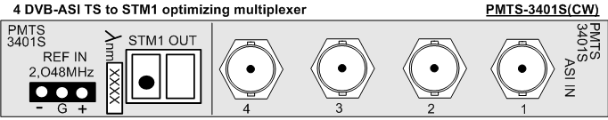
PMTS-3401 rear panel view:
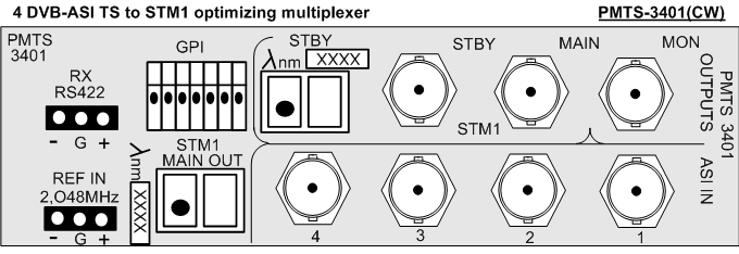
PMTS-3401 controls and indicators
All the controls and indicators are located at the edge of the frontal module
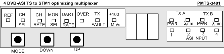
The following LED indicators exist:
- REF – lit when the REF IN signal is present
- TX FAULT – lit when:
- any laser fault (optical power less than -3dBm)
- SFP module is extracted/absent
- OVER – lit when the DVB-ASI input data rate exceeds the preset limit
- ASI INPUT 1/2/3/4 – lit when an input DVB-ASI signal is detected
The MODE button toggles through the me nu , the UP and DOWN buttons edit m enu entries.
Multiplexer setup
- DVB- ASI input number selection.
Toggling the MODE button select the CH. SEL(channel select) mode. Pressing the UP and DOWN buttons select an input.
Available options are: 1 / 2 / 3 / 4
In a case of input data rate exceeding the preset limit, the OVER LED lits up and the o ( overflow ) character appears along the relevant input number.
For example : 1o / 2o / 3o / 4o
- Presetting the maximum allowed input datarate
Toggling the MODE button select the CH. RATE (channel rate) mode. Pressing the UP and DOWN buttons adjust the maximum input datarate limit in the 0,8 ~ 120 Mbps range with 0.1 Mbps increments. This limit is valid for the DVB-ASI input selected in the previous menu entry.
The values above 100 Mbps are denoted by the +100 Mb/s LED, the main display shows the three lower decimal digits.
For example:
The +100 Mb/s LED is OFF, 12.5 on the main display means 12.5 Mbps.
The +100 Mb/s LED is ON, 12.5 on the main display means 112.5 Mbps.
Please note: if one of input DVB-ASI TS has a limit-exceeding datarate, this TS will be processed only when the combined output datarate does not exceed the 120Mbps value. If this 120Mbps limit is exceeded – the offending TS is dropped.
- Selecting an input for monitoring (PMTS-3401 model only)
Toggling the MODE button select the MON SEL (monitor select) mode. Pressing the UP and DOWN buttons choose an input number.
Available options are: 1 / 2 / 3 / 4
- RS-422 bitrate presets (PMTS-3401 model only)
Toggling the MODE button select the UART RATE mode. Pressing the UP and DOWN buttons choose the RS-422 bitrate.
Available options are: 2.4 kb/s, 4.8 kb/s, 9.6 kb/s, 19.2 kb/s, 38.4 kb/s, 57.6 kb/s, 115 kb/s
- The MAIN laser output optical power display
Toggling the MODE button select the TX A PWR (Tx A power) mode.
The main display shows the output optical power in dBm.
For example: the 2.8 corresponds to «+2.8 dBm», the -2.8 corresponds to «-2.8 dBm » optical power.
- The MAIN lasers' wavelength display.
Toggling the MODE button select the TX A ? nm mode.
The main display shows last three digits of the wavelength.
For example: 550 corresponds to 1550nm, 310 corresponds to 1310nm.
- The STDBY laser output optical power display
Toggling the MODE button select the TX B PWR (Tx B power) mode.
The main display shows the output optical power in dBm.
For example: the 2.8 corresponds to «+2.8 dBm», the -2.8 corresponds to «-2.8 dBm » optical power.
- The STDBY lasers' wavelength display.
Toggling the MODE button select the TX B ? nm mode.
The main display shows last three digits of the wavelength.
For example: 550 corresponds to 1550nm, 310 corresponds to 1310nm.
Hot-swapping an SFP module.
SFP optical module features one or two LC-type optical connector(s) and has the standardized electrical interface.
In case of SFP module failure it is possible to replace it without powering the whole system down.
The remote control and management from a PC
All the PROFLEX™ modules are remote controllable from a PC. This facility is available if a rack is fitted with a CPU module (ordered separately). |